
We aim to measure the photospheric radius of the Sun by recording an accurately timestamped video of the eclipse flash spectrum.
The simplest way to add timestamping to a video is to record the audio of a beeping signal synchronized with UTC. https://occultations.org/observing/educational-materials/equipment/dslr/dlsr-time-synch/
With the timing device we have designed, we can achieve a synchronization with UTC which is better than 1ms
Some GPS devices provide a dedicated output called 1PPS (one peep per second). This output generates a train of square waves the leading edge of which is synchronized with the start of every UTC second. The signal is taken from the atomic clocks which are on board of the GPS satellites. By triggering on the leading edge of this signal, we can generate a train of audible beeps that is synchronized at better than 1ms with UTC. Recording this audio with the flash spectrum video will provide the time stamping.
The GPS time device is very easy to use. It runs on batteries and when it is switched on, the user just need to press a button and the device starts beeping away. As it relies on GPS signals, the device can be used anywhere in the world.
The device is built almost entirely from pre-made electronic circuits. Its brain is an Arduino micro-controller with on top a GPS shield and an RGB LCD display. The external GPS antenna provides good signal quality in all circumstances.
The GPS time device relies on the 1PPS signal from the GPS antenna and the buzzer produces 125ms long beeps every second, 250ms long beeps every tenth second and 500ms long beeps every minute.
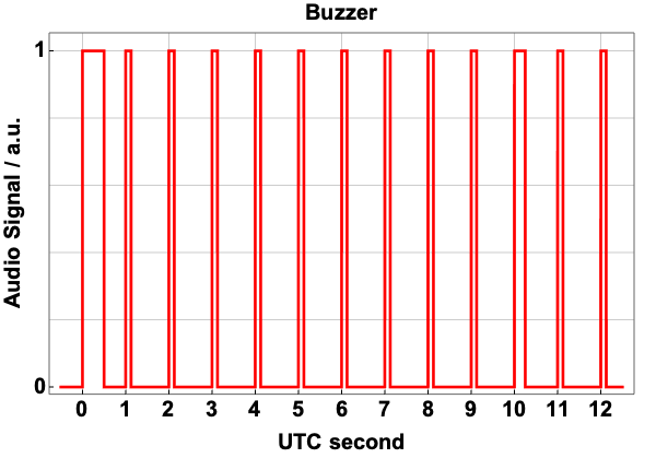
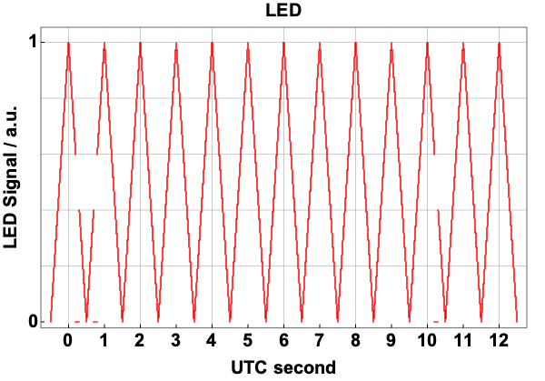
There is also an LED thats is going on and off every second in a triangular shaped way to measure the audio/video lag of the camera or to allow a possible setup in which some light could be recorded on the sensor itself. We came across this idea while searching for time-stamping methods years ago (F. Suits, “Methods for Timestamping Analog and Digital Video”, 2014, the presentation used to be found here: http://www.altazinitiative.org but it does not seem to be available any longer). The light signal is at its maximum at the beginning of every second and goes to zero in the middle of the second. To identify the seconds, “notches” appear on the signal corresponding to specific seconds. A notch is a short dip on the descending or on the ascending ramp of the triangular signal. If a second is a multiple of 10, a notch appears on the descending ramp. If a second starts a minute, a notch appears both on the descending and on the ascending ramp. The linearity of the signal is obtained by powering the LED at constant 5V and producing the ramps by PWD (Pulse width modulation).
The code that runs the device is written in C and it is executed by the microcontroller on the Arduino board. An hardware trigger listens to the GPS 1PPS signals and, as soon as the leading edge of the square wave is detected, the value of the Arduino internal microseconds timer is collected. This value is then used, together with the running microsecond timer, to command the buzzer and the LED.
One issue of using the microsecond timer is that the ceramic oscillator of the Arduino microcontroller is not very stable. It should tick exactly 1 million times every second but, in reality, it usually ticks slightly less (i.e. 999300 times). Temperature is the main driver of this instability. The code compensates for this by measuring the number of times the microsecond timer ticks between the start of two consecutive UTC seconds (relying on the interrupts triggered by the 1PPS signal) and computing a scaling factor to correct the output of the microsecond timer.
Computing the scaling factor and listening to the serial communication from the GPS (providing information about the label of every UTC second, i.e. 15h 49m 32s UTC) happen while the timing device is in the waiting state before controlling the buzzer and the LED. Once the button is pushed, all serial communications and scaling computations are suspended, so not to introduce undue delays in the timing routine.
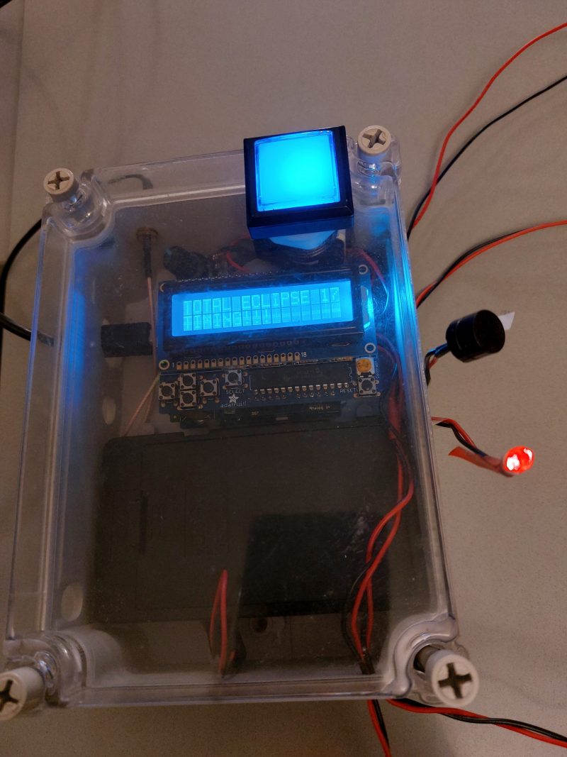
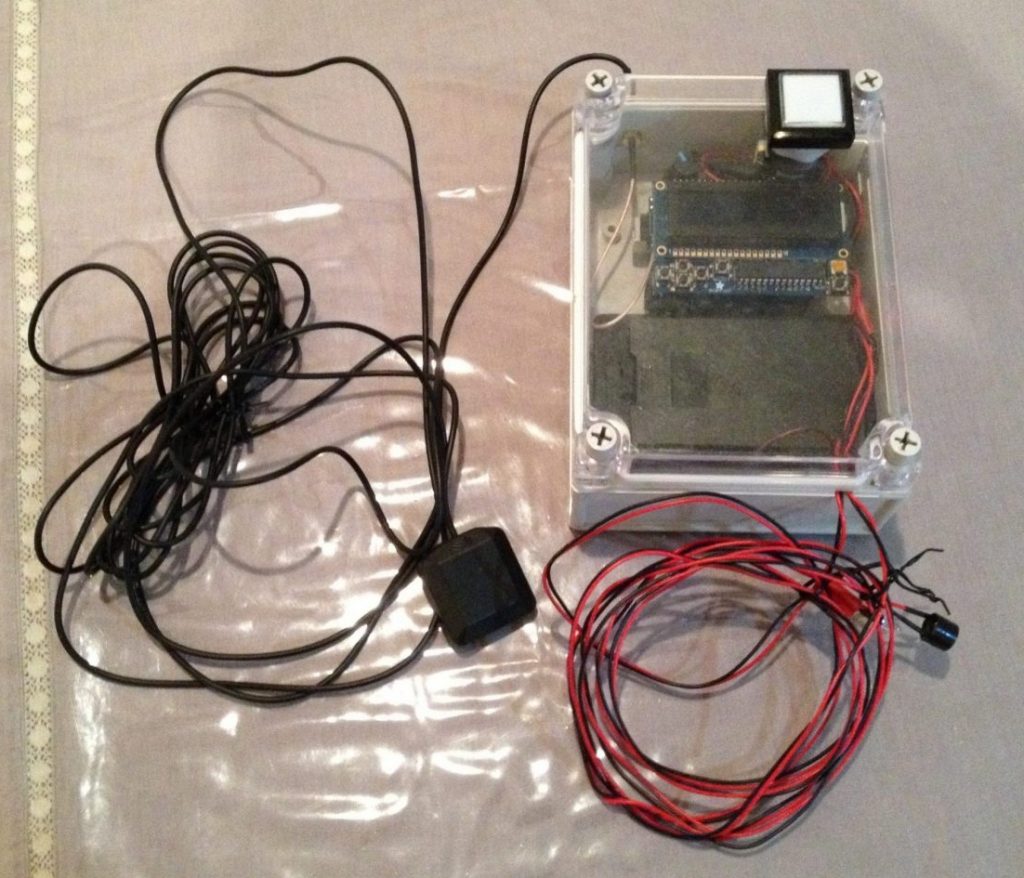
Building this timing device requires some soldering and some work to assemble all the components. The spare parts are around USD200 and it takes 2-3 hours to assemble

Pingback: Flash Spectrum Recording Guidelines - Besselian Elements